Border Gateway Protocol (BGP) vs. Static Routing (Charts Included)
Learn about the design differences between BGP Routing and Static Routing in the context of a private network with a private Autonomous System Number (ASN).

Mar 31, 2022
SHARE
For anyone who has ever been in charge of managing an enterprise network, you are likely aware that there are several dynamic routing protocols that can help alleviate all of the error-prone, human touch points of network expansion.
You might be less aware, however, with how dynamic routing works in comparison to static routing.
The goal of this blog is to walk you through the design differences between setting up a network using Border Gateway Protocol (BGP) Routing vs. Static Routing (in the context of a private network with a private Autonomous System Number or ASN).
Sexy Networking Diagrams (copywrite pending) by Matt Pinto
First things first:
If any of the terms in this introduction are new to you, I recommend that you skip ahead to the “Key Concepts” section at the end of this post.
This post includes multiple custom network diagrams. The IP addresses used in these images are entirely random.
For anyone that reads this and thinks to themselves, “Wait, what about the firewall?” Yes, the firewall is supposed to go between the LAN and the network, but I’m trying to keep this blog focused solely on explaining BGP, ok?
Scenario 1a - Static routing between two locations.
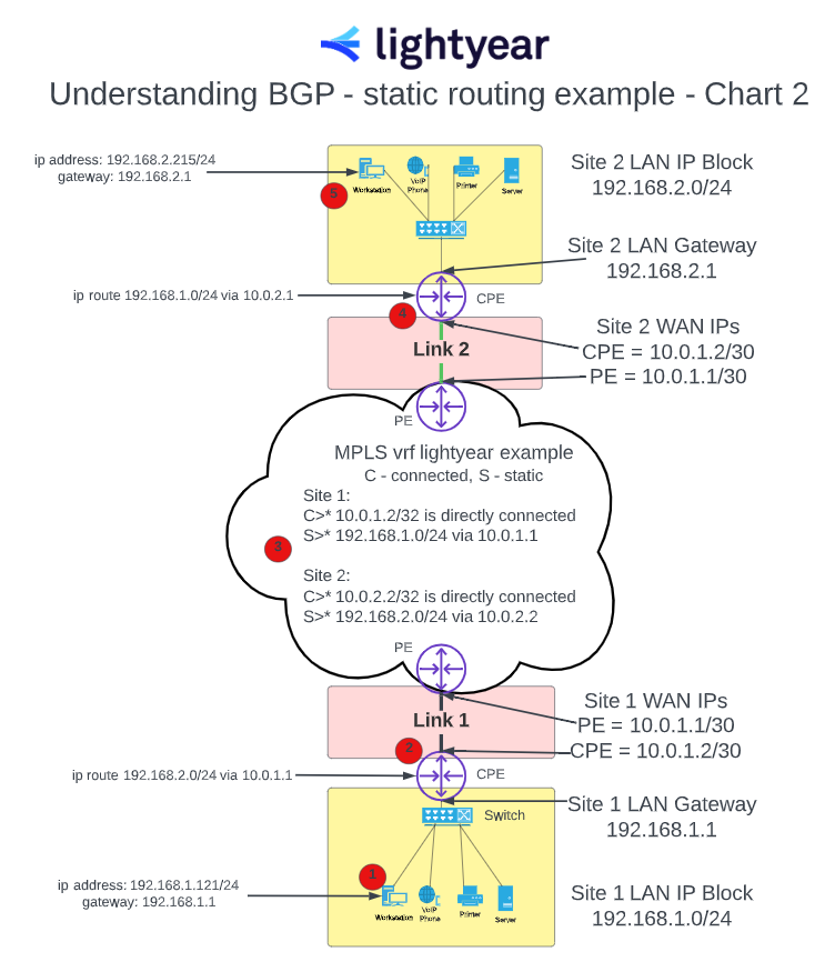
In Chart 2 below, I’ve attempted to provide an extremely rudimentary explanation of how static routing takes place when moving data between two locations connected via MPLS. If there was an “IP Routing 101” class, this would be more like “Intro to IP Routing”.
For any of the advanced networking people reading this - yes - adding a default route in the CPE routers pointing all traffic to the vrf would be a simple fix for static routing in the CPE routers. Reminder that the point of this is to show the difference between static routing and BGP routing.
Chart 2
Situation = PC at site 1 (192.168.1.121 - Chart 2, red dot 1) is attempting to connect to PC at site 2 (192.168.2.215 - Chart 2, red dot 5).
Sexy Networking Diagrams (copywrite pending) by Matt Pinto
Chart 2 Reference Notes
The traffic will initially go to the PC’s default gateway. In this example, the CPE router is the PC’s default gateway. In a static routing scenario, the CPE Router needs one of the company’s IT engineers to configure a static route saying that traffic destined for 192.168.2.0/24 has to go to 10.0.1.1 - the PE router at the other side of the WAN link. (see Chart 2 - red dot 2)
The traffic is now at the PE router which was configured by the service provider’s engineer. In a static routing scenario, two static routes need to be configured into the VRF for this instance (see Chart 2 - red dot 3). One route (example 192.168.2.0/24 via 10.0.2.2) so that this traffic knows how to get to site 2. A second route (example 192.168.1.0/24 via 10.0.1.2) so that the return traffic knows how to get back to site 1.
At this point, the vrf router that is configured by the service provider has the information that it needs to forward the traffic to the CPE router at site 2.
The router at site 2 knows about the PC (192.168.2.215) because it’s directly connected, but it needs the return route so that the PC at site 2 can send traffic back to the PC at site 1. Example 192.168.1.0/24 via 10.0.2.1. (see Chart 2 -, red dot 4)
The end of the process is when the connection is established between the PC at site 1 and the PC at site 2 (see Chart 2 - red dot 5) and they are able to directly communicate with each other.
Notice in this example that there are multiple points along the way that require manual configuration by engineers so that the equipment knows about the next place to send traffic.
The customer’s in-house IT engineers need to configure the CPE routers at both Site 1 and Site 2. The service provider’s engineers have to configure the PE/vrf in the middle to enable the site to site traffic to function. There are no technical reasons that this wouldn’t work. As a matter of fact, it will work just fine and in a static network with very few or no changes this is a perfectly suitable WAN configuration. The issue comes in when you start talking about the time and coordination required to add another site.
Scenario 1b - Adding a new location with static routing.
Ok, so what if you want to add a new site to your network on static routing?
Chart 3
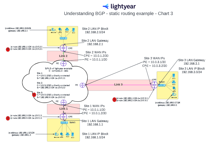
I created chart 3 to illustrate the amount of direct human interaction required to add a site to this topology.
Sexy Networking Diagrams (copywrite pending) by Matt Pinto
Chart 3 Reference Notes
Here are the manual routing steps required to add a location to a static routed network.
Customer’s IT engineer has to enter static routes in the new CPE router at site 3. (see Chart 3 - red dot 1)
Customer’s IT engineer has to enter a static route in the CPE router at site 1 for traffic towards site 3. (see Chart 3 - red dot 2)
Customer’s IT engineer has to enter a static route in the CPE router at site 2 for traffic towards site 3. (see Chart 3 - red dot 3)
Service provider’s engineer has to enter a static route in the vrf. (see Chart 3 - red dot 4)
Scenario 2a - Adding a new location with BGP routing
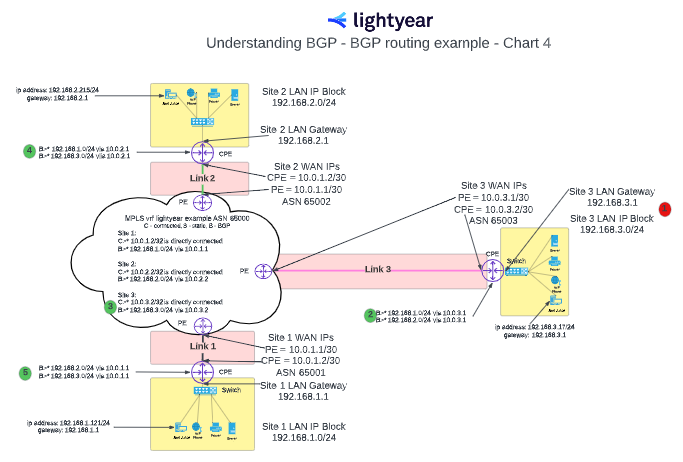
In contrast to scenario 1, when BGP routing is enabled and set up, routes are automatically shared between the CPE router(s) and the vrf. Then the vrf automatically redistributes the IP route information with all the CPE routers that are setup to BGP peer with the vrf.
Chart 4
I created Chart 4 using the same network topology to illustrate the (relatively easy) process of adding a third location to a BGP enabled network.
Sexy Networking Diagrams (copywrite pending) by Matt Pinto
Chart 4 Reference Notes
Customer’s IT engineer has to configure the router for site 3 with the appropriate IP addresses and BGP peering with ASN. (see Chart 4 - red dot 1)
The router will advertise the IP block from the site at the same time as it learns the other IP Subnets from the vrf. (see Chart 4 - green dot 2 and 3)
Once it learns the new IP address for site 3, the vrf will then advertise the routes to site 1 and site 2. The CPE routers at site 1 and site 2 will learn the routes and automatically add them to their route tables. (see Chart 4 - green dot 4 and 5)
Scenario 3a - Public BGP peering
If I haven’t lost you by now, the last concept should be a little easier: public BGP peering. Almost all of the same principles apply to both private and public BGP peering.
If a router is set up with a BGP public peering session, the IPs that it advertises will be routed automatically to that site via the public internet.
There are other variables that I’m not going to cover regarding the process, such as securing a Public ASN from ARIN and the proper Letter of Authorization forms must be completed and put on file with the Internet Service Providers (ISPs).
Multihoming is the practice of connecting your network to multiple internet service providers (ISPs). There are several use cases for multihomed public BGP peering, the most common of which is used for network diversity.
Chart 5
Here’s what it looks like:
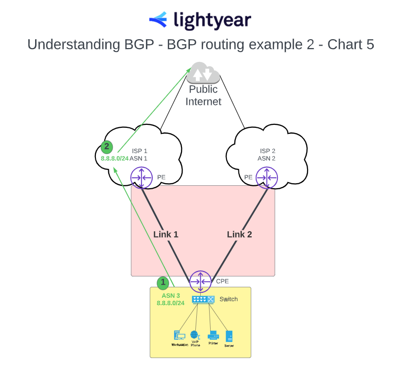
Sexy Networking Diagrams (copywrite pending) by Matt Pinto
Chart 5 Reference Notes
Customer’s IT engineer configures the CPE router for BGP peering and advertises the public IP block to ISP 1’s PE router. (see chart 5 - green dot 1)
ISP 1’s PE router forwards the IP block to the public internet and then traffic bound for that subnet will route inbound over ISP 1’s network through their peering and transit connections. (see chart 5 - green dot 2)
Scenario 3b - How to handle network outages with public BGP peering
There are several reasons to change BGP advertisement to the secondary ISP. The main one being network issues with the link to ISP 1. In that event the public IPs can be moved to the secondary ISP.
Chart 6
Here’s what it looks like:
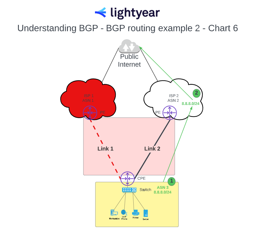
Sexy Networking Diagrams (copywrite pending) by Matt Pinto
Chart 6 Reference Notes
Customer’s IT engineer configures the CPE router for BGP peering and advertises the public IP block to ISP 2’s PE router. (see Chart 6 - green dot 1)
ISP 2’s PE router forwards the IP block to the public internet and then traffic bound for that subnet will route inbound over ISP 2’s network through their peering and transit connections. (see Chart 6 - green dot 2)
Key Concepts
Hello! I saved this section for last so we could skip to the good stuff above, but here are a couple of key concepts that we build on in this post.
WAN & LAN
If you’re reading this post, you probably don’t need these definitions, but for the avoidance of doubt…
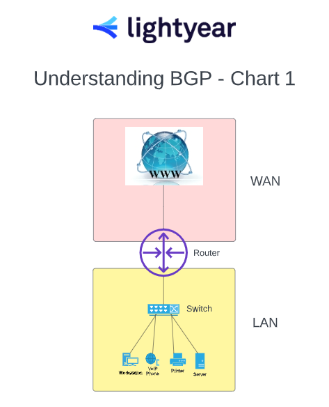
Local Area Network (LAN) = The environment and devices that are all directly connected to each other at a location. For example, PCs, VoIP phones, printers, and servers. See chart 1 LAN
The LAN Gateway or designated gateway is the router IP address/network node that serves as an access point to another network, often involving not only a change of addressing, but also a different networking technology. (see chart 2)
Wide Area Network (WAN) = The connectivity from the site to the rest of the world.
Router
Router = A device that sends information and bridges networks together. In this blog, we’re going to focus on three types of routers.
Customer Premise Equipment (CPE) Routers = Installed at the customer site and programmed by the customer’s IT department’s engineers. (see Chart 1)
Provider Edge (PE) Routers = Installed in the service provider’s network and are programmed by the service provider’s engineers. (see Chart 1)
Virtual Routers (VRF) = Virtual Routing and Forwarding. Building a VRF is a way to isolate specific customer instances that are built on the same PE. Connections within a VRF can see each other, but they are not part of the global or public route tables and are considered private. Typically, an instance inside of a VRF represents a site for a multi location customer. There are normally more than one instance (or site) within a VRF. (ref Chart 2)
IP Address
The IP address is how computers identify devices on the internet or a local network. IP stands for "Internet Protocol," which is the set of rules that govern the format of data sent via the internet or local network.
Almost every PC knows what its local IP address is and what its default gateway is. PCs typically learn their IP address and Gateway via a process called Dynamic Host Configuration Protocol - DHCP. I cover the DCHP process in Chart 2 (see chart 2 - red dot 1)
Dynamic Routing Protocols
There are several dynamic routing protocols that can help alleviate all of the human touch points when a new location is added to a network.
A few of the more popular dynamic routing protocols are OSPF (Open Shortest Path First), EIGRP (Enhanced Interior Gateway Routing Protocol, RIP (Routing Information Protocol), and of course BGP (Border Gateway Protocol). There are several others, but these are a few of the most commonly used protocols.
They each have their own valid use cases, but in this post we’re just going to focus on BGP routing.
Border Gateway Protocol (BGP) Routing
Border Gateway Protocol (BGP) is a dynamic network protocol that uses predetermined standards to facilitate communication between network devices. BGP has been likened to a country's postal system — both seek the fastest among multiple routes to deliver data between a sender and recipient(s).
Autonomous System Number (ASN)
Autonomous System Number or ASNs are used to basically setup peering between routers so that they can exchange route information.
ASNs, much like IP addresses, are set up as Public and Private. In this private network example, private ASNs should be used.
Conclusion
I hope you found this post helpful in visualizing BGP and static routing.
If you have any questions or suggestions for future content please reach out to me at [email protected]
Want to learn more about how Lightyear can help you?
Let us show you the product and discuss specifics on how it might be helpful.
Not ready to buy?
Stay up to date on our product, straight to your inbox every month.